Post by londonman on Jan 4th, 2018, 12:12pm
Can someone please confirm that I am correct in my thinking ?
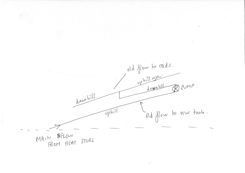
The first photo is a rough drawing of how the CH layout used to work. The pump was located in the garage by the heat store. The pump fed a metre into the house where the feed split to two motorised valves. One valve sent the hot water down a dedicated pipe to the hot water cylinder. The second valve fed the CH feed and about another metre after this valve it split to feed the upstairs rads and downstairs rads. Within feet of where the split occurred, this feed pipe was hitting the radiators that it was designed to feed. Assuming that the system was reasonably balanced then my argument is that the temperature in this feed pipe is going to be roughly that when it left the heat store...give or take the odd degree.
NB the diagram does not show the CH split to the downstairs rads.
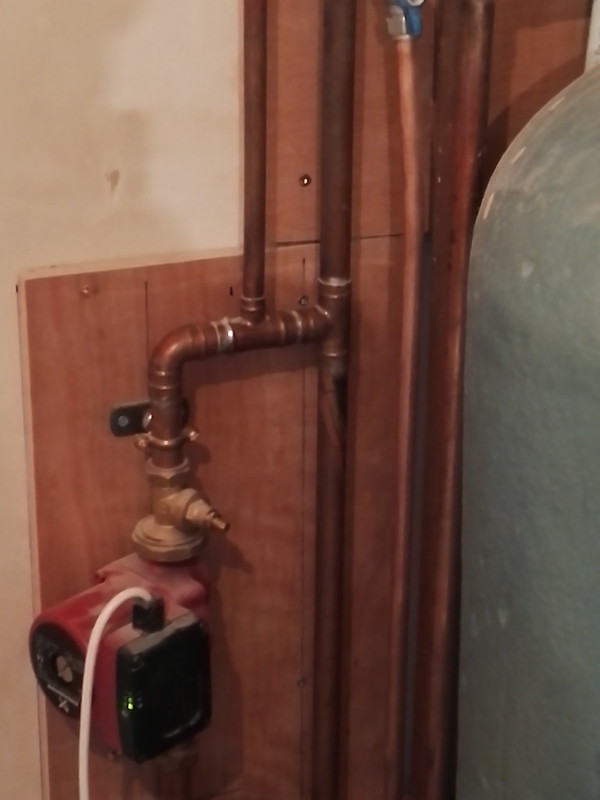
Now when my plumber put in the new boiler he was very fixated on neutral points and insisted that the pump be relocated up at the hot water tank and the feed and vent pipes connected there to create the neutral point. However this meant that the motorised valves needed to be located here as well which in turn necessitated modifications to the primary hot water feed.
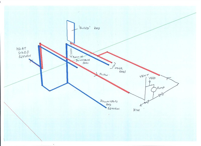
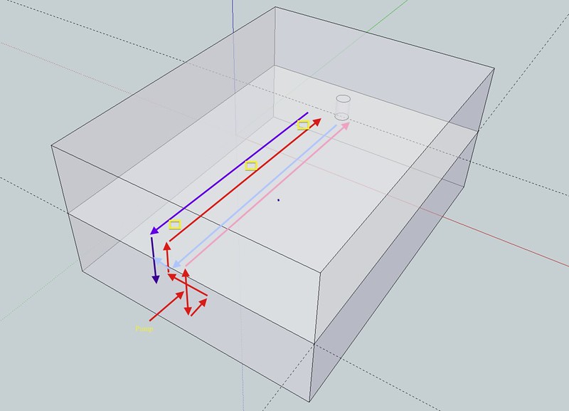
The two original valves were removed and the T between HW and rads removed. The feed to the rads was cut off and blocked. The original and remaining feed to the HW tank became the main feed to the new pumps' location. Two new valves after the pump...the one we're interested in...the CH rad one then feeding a new pipe that T'd in part way down the upstairs original CH feed run.

With this new arrangement, I am 11 degrees of heat lower at the pump then that leaving the heat store because of the long run now built in to the system due to the new layout. 66 degrees leaving the heat store (don't worry about whether this is high enough etc for the purposes of this discussion) and 55 degrees when it hits the actual CH upstairs rad circuit. My plumber does not accept this. He says that I'd see the same thing on the original system which I think is bonkers. Original system...distance between heat store and first rad ...4m. New system...distance about 30m.
A pressurised system was and is out of the question as there was existing inaccessible pipework underneath the floorboards with joints of unknown provenance and as I'd already discovered one joint that wasn't properly soldered, I think this decision is sound.
Supplementary question. The furthest radiators from the CH feed point are in the kitchen. With every other radiator and HW tank off, the hottest temperature of the incoming CH water to these rads is a meagre 36 degrees. Is this an indication of an under-powered pump or a blockage in the old pipework ?
Second supplementary question. My plumber says that you get different temperature readings if the pipe is vertical or horizontal. EG horizontal copper pipe coming to a 90 degree feeding the vertical pipe into the radiator tail. Doesn't make sense to me.